Crank was
successfully balanced by a local machine shop, J.B.Precision, to a
balance factor of 50%. The computer model of the crank and
counterweights turned out to be pretty accurate because the shop didn't
have to remove too much metal to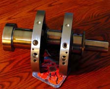 get the balance just right. The crank will be re-balanced to 60% with
the larger counterweights attached. This will make it easy to evaluate
two different balance factors when the motor is ready to run.
Counterweights can be unbolted and removed through the sump without any
other motor disassembly.
get the balance just right. The crank will be re-balanced to 60% with
the larger counterweights attached. This will make it easy to evaluate
two different balance factors when the motor is ready to run.
Counterweights can be unbolted and removed through the sump without any
other motor disassembly.
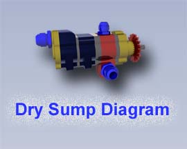 Still
waiting for quotes for the cylinder machining so onward to sump and oil
pump design! Bill Dailey at Dailey Engineering is making a pump for the
motor and has been very helpful with info on dry sump oiling system
layout. Still
waiting for quotes for the cylinder machining so onward to sump and oil
pump design! Bill Dailey at Dailey Engineering is making a pump for the
motor and has been very helpful with info on dry sump oiling system
layout.
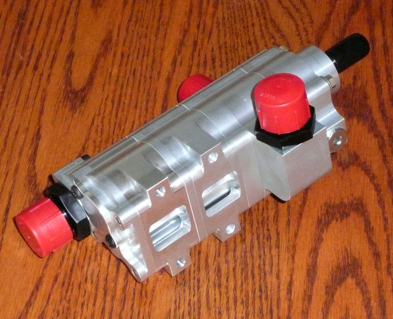
Received oil
pump from Dailey Engineering and it's a very beautiful piece
of machining and engineering!
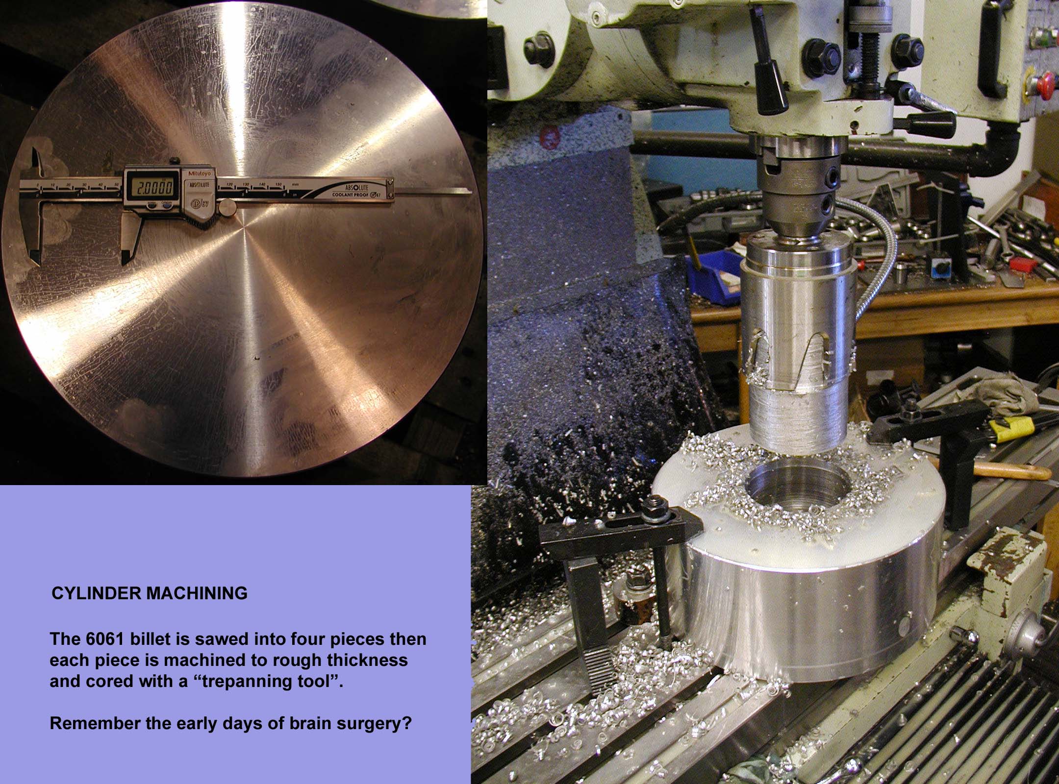
Finally made a decision on the cylinder machining!
Foreman CNC is going to make two front and two rear cylinders. There
aren't too many local machine shops that can turn something this big on
their CNC lathes. Here
are a few images of the first machining operations for the cylinders.
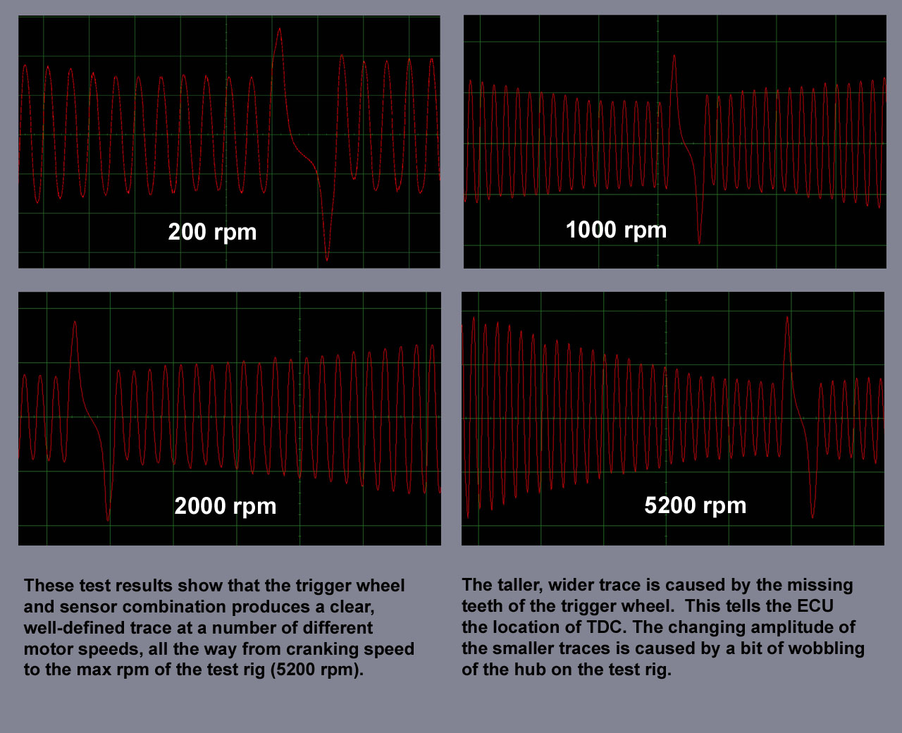
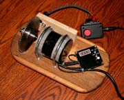 A test rig for evaluating trigger
wheels and sensors is finished. The sensor signal can be viewed on an
oscilloscope at different crank speeds and wheel-to-sensor air gaps. It
is important to have a good, sharp series of pulses at cranking speed
and at maximum RPM. Here are some images of traces
recorded at several different motor speeds. A test rig for evaluating trigger
wheels and sensors is finished. The sensor signal can be viewed on an
oscilloscope at different crank speeds and wheel-to-sensor air gaps. It
is important to have a good, sharp series of pulses at cranking speed
and at maximum RPM. Here are some images of traces
recorded at several different motor speeds.
Once the crank trigger wheel and
sensor are sorted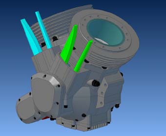 out we will be ready to see about
getting some cases made! out we will be ready to see about
getting some cases made!
The upper and lower case design mods
are nearly finished. Most of the changes have been done to make the
machining easier. The attached 3d pdf shows most of the latest design
updates.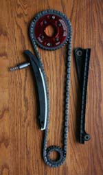
Not much progress over the last few
months. Still fiddling with final details on the case designs. Changes
were required to incorporate the chosen cam gears and chains. For the
prototypes, chains, gears, guides and tensioners from a Ford 4.6l
modular motor (recent Mustangs) will be used. The chains
should be strong enough for our application and after-market
accessories like adjustable cam sprockets are easily found.
Spiralock taps will be used to cut
all the fastener threads in the cases. These taps have a special shape
that helps to keep the studs and fasteners from loosening with
vibration and thermal cycling. Threading and evaluating test pieces of
aluminum is underway.
All the fastener lengths and sizes
are sorted out. ARP studs, nuts and bolts will be used.
The front lower cam drive is shown
in the picture, featuring both an adjustable cam sprocket and crank
sprocket. The upper cam drive details are still not nailed down but
case machining ahould be started soon.
All the cam drive sprockets,
link-belts and roller chains have been finalized and sourced from
Cloyes Gear and Products. Their tech services department was helpful in
finding chains with the right pitch and number of links. Thanks Mike!
New models of the cylinder head are
almost completed. The first version would have been very difficult to
machine. The current version has a number of changes to simplify
machining, plus two more parts. Updated 3D pdf to come soon!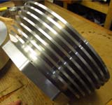
Bill is concentrating on learning
more about CAM programming. After talking to
a number of CNC machine shops it seems like a good idea to re-do the
CAD models of the upper and lower cases to make them easier and less
expensive to machine. By working out the actual toolpaths and times
required to make the parts the model shapes can be optimized so that it
might be possible to machine them more quickly and to use a 4-axis
Vertical Machining Centre instead of a 5-axis VMC.
Meanwhile, Foreman CNC has been able
to find some time to move ahead with the cylinder machining!
go to page 1
3
|


